
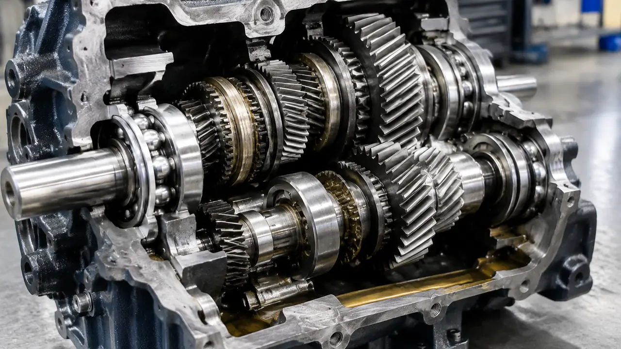
Start with the gear forces
Every gear mesh produces a force on the shaft, and the direction of that force sets the bearing type. A spur gear mainly pushes the shaft sideways, which is a radial load. A helical gear adds an axial component because its teeth are cut at an angle. A bevel gear produces both radial and axial forces, and the axial part reverses direction when the rotation reverses. A worm gear produces a high axial thrust on the worm shaft. Before comparing catalogue pages, sketch the shaft, mark the gears and draw the forces; the bearings follow from the drawing.
Each shaft needs two bearing positions. One bearing, the locating bearing, fixes the shaft axially. The other, the non-locating bearing, carries radial load only and lets the shaft grow with temperature. Mixing up the two roles is a common design mistake, and it is why a gearbox bearing list is more than a list of designations.
Matching load path to bearing type
| Gear or stage | Load pattern | Common bearing choice |
|---|---|---|
| Light spur stage, input shaft | Mainly radial, fairly high speed | Deep groove ball |
| Helical gear shaft | Radial plus moderate axial | Paired angular contact or tapered roller |
| Bevel gear shaft | Radial plus axial in one main direction | Tapered roller pair, set with preload |
| Heavy output shaft | High radial, shock | Cylindrical roller and a locating bearing |
| Worm shaft | High axial thrust | Tapered roller pair or angular contact pair |
| Tight radial space, planetary | High radial in thin section | Needle roller |
The table gives starting points, not a design. Actual sizes follow from the ISO 281 life calculation with the gearbox duty cycle, which the designer or the original manufacturer holds. When you buy a replacement, the safest route is to use the original designation and verify it against the datasheet.
Why tapered rollers dominate heavy gearboxes
A tapered roller bearing carries radial and axial load together and is separable, so the cone with its rollers and the cup can be fitted independently. Two of them mounted opposed to each other make a stiff shaft support that can be adjusted. The adjustment, called setting, controls the end play or preload and is crucial for gear mesh quality. Too little preload lets the shaft move and the gears hammer; too much raises temperature and shortens life. The details are in the tapered roller bearing page, and metric tapered bearings follow ISO 355 for boundary dimensions.
Where cylindrical rollers and balls fit
Cylindrical roller bearings carry heavy radial load for their size. Types with ribs on both rings can also locate the shaft against small axial forces, while types with a rib-free ring let the shaft slide, making them natural non-locating bearings. The type letters (NU, NJ, NUP, N) are explained in the cylindrical roller bearing types note. Deep groove ball bearings suit light, fast input stages where load is low and noise matters. For paired angular contact bearings the mounting arrangement (face to face, back to back or tandem) changes stiffness and axial capacity, as shown on the angular contact page.
Fits, shoulders and mounting details
A well chosen bearing still fails if the mounting is wrong. In a gearbox the inner ring usually turns with the shaft under load, so it needs an interference fit, while the outer ring sits in a housing bore that is often cast iron or aluminium. Aluminium expands more than steel, which loosens the outer ring fit as the gearbox warms up. Designers allow for this with tighter housing fits or a steel insert. The shaft shoulder and the housing shoulder must also be square and the right height, so that the face of the ring is supported without rubbing the cage or seal. Fillet radii on the shaft must be smaller than the chamfer on the bearing, or the ring will not seat. These details are tabulated in the shaft and housing fits note and in the supplier datasheet.
Axial location needs thought as well. A snap ring, a locknut with a tab washer or a spacer sleeve can hold the locating bearing, and the right choice depends on the axial force. Components such as locknuts, lock washers and sleeves are sold with bearings for that reason, and it is cheaper to order them together than to discover a missing nut at assembly.
Finally, think about heat. A gearbox bearing runs hotter than the housing surface suggests, because oil temperature rises with load and gear churning. If the thermal expansion of the shaft is blocked, the non-locating bearing will be pushed into axial load that it was never designed to carry. Allow the shaft to float at that position, and the bearing life will follow the calculation.
Lubrication and sealing in the gearbox
Most gearboxes lubricate their bearings with the same oil that lubricates the gears, either by splash or by circulation. That oil carries wear particles and sometimes moisture, so the bearings in a gearbox see a dirtier environment than their catalogue suggests. Grease-lubricated gearboxes, such as small reducers, use sealed bearings or shields to hold the grease in. The choice between them is covered in oil vs grease lubrication. A bearing running in oil usually needs an open design, not a sealed one, so the oil can pass through freely. Mixing sealed bearings into an oil-lubricated stage starves the rolling elements and causes premature failure.
Replacement checks that save time
- Read the full designation from the old bearing, including suffixes for clearance, cage and tolerance class.
- Note which bearing is locating and which is non-locating, and keep that role.
- Check whether the pair is a matched set; paired tapered or angular contact bearings may need to be ordered together with the correct setting.
- Record the shaft and housing diameters and the oil type.
- Look at the damage pattern of the old bearing before ordering the new one; a pattern that points to misalignment or contamination calls for a fix, not just a replacement. The reading of failures is covered in bearing failure causes.
Sourcing gearbox bearings through the desk
Gearbox programmes often mix several families in one bill of materials: tapered rollers for the output, cylindrical rollers for a middle shaft, deep groove balls at the input. The desk groups those lines across partner bearing plants, keeps the designations and clearance groups in one record, and reports batch data by lot. Typical MOQ and lead time ranges are on the MOQ and lead time page, and are confirmed in writing for each program. Send the bill of materials through the quote form.