
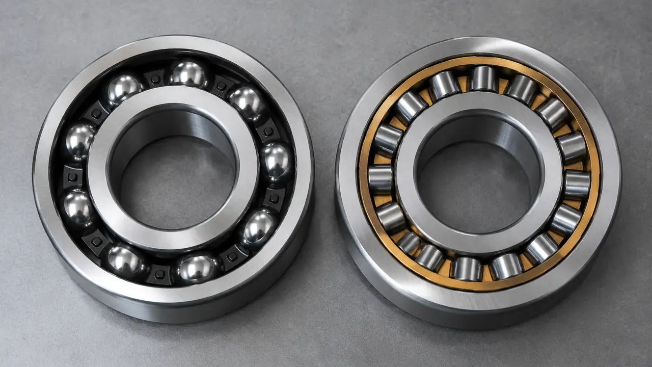
Two roller shapes, two jobs
A cylindrical roller bearing uses straight rollers running parallel to the shaft between a pair of rings. The contact is a line along the length of each roller, which gives a high radial capacity in a compact section. A tapered roller bearing uses conical rollers between a cone (inner ring) and a cup (outer ring), with the raceways angled so that the lines of contact meet at a point on the shaft axis. That angle is what lets it take axial load as well as radial.
The practical result is simple. Cylindrical rollers suit shafts that need to carry a heavy radial load, spin relatively fast and perhaps float axially. Tapered rollers suit shafts that carry heavy radial and axial load together and need to be located firmly, such as wheel hubs, gearbox shafts and axles. The two families sit in neighbouring parts of the catalogue, under roller bearings.
Side-by-side comparison
All comparisons are relative. Ratings, limiting speeds and exact dimensions come from the supplier datasheet for the designation, with nominal dimensions per ISO 355 for metric tapered types and ISO 15 for cylindrical types.
| Criterion | Tapered roller | Cylindrical roller |
|---|---|---|
| Load direction | Radial plus axial in one direction; pairs locate the shaft both ways | Radial; axial only with NJ, NUP or flanged types, and then limited |
| Load capacity | High combined load; very good for shock | Very high radial load in a compact section |
| Speed | Medium; friction at the roller end limits it | Higher than tapered at the same size |
| Misalignment tolerance | Low; sensitive to shaft deflection | Low; sensitive to edge loading |
| Friction and noise | Moderate torque; depends strongly on setting | Lower torque; quiet when properly loaded |
| Maintenance | Needs correct axial setting or preload at assembly | No setting; axial float is built in for NU and N types |
| Typical applications | Wheel hubs, axles, gear reducers, agricultural drives | Gearboxes, large electric motors, pumps, machine tools |
| Relative cost factors | Matched cone and cup, metric and inch sets, setting effort | Several ring configurations, precision grinding of rollers |
Axial load: the deciding factor
The question that usually separates the two is axial load. A tapered roller bearing takes axial load in one direction through its angled contact, so shafts that must be fixed against axial movement use two tapered bearings mounted face to face or back to back. This arrangement is stiff and carries combined load well, which is why it appears in wheel hubs and gearbox shafts.
A cylindrical roller bearing in its basic NU or N form carries only radial load, and the rings can move axially relative to each other. This is useful on a shaft that expands with temperature, where one bearing fixes the shaft and the other floats. Types NJ and NUP add flanges to take a small axial load or to locate the shaft, but they do not carry the large axial loads that tapered bearings do. The NU, NJ, NUP and N types are described in their own note.
Speed, friction and heat
In a tapered roller bearing, the roller end presses against a rib on the cone, and the rubbing at that contact is the main source of friction and heat. As speed rises, this limits the bearing. A cylindrical roller bearing has only light rubbing at the roller ends and can run faster for the same size, which is why large motors and high-speed gear stages often use it as the radial support.
Friction in a tapered bearing also depends on how tightly it is set. Too loose and the rollers wander and the shaft moves; too tight and friction and temperature rise quickly. Setting is therefore part of the assembly procedure, not an afterthought.
Setting, preload and assembly
Because the contact is angled, a pair of tapered roller bearings must be set to a defined axial clearance or preload. The correct value depends on shaft stiffness, speed and expected temperature, and it is normally written in the equipment manual. Installers adjust it with shims, a nut or a spacer. Cylindrical roller bearings need no such setting, although the housing and shaft fits are more critical because the rings are thin and follow the shape of their seats. Both types are separable, so inner and outer parts can be fitted independently with tight press fits. The inner assembly of a cylindrical bearing can often be mounted and removed without disturbing the outer ring, which helps maintenance.
Inch and metric sets
Tapered roller bearings are common in both metric and inch sizes. Many vehicle and agricultural hubs use inch cone and cup numbers, while industrial gearboxes use metric designations under ISO 355. Cylindrical roller bearings are almost always metric. If you replace an inch tapered bearing, check that the cone and cup pair is complete and that the numbers are compatible, as covered in inch vs metric bearings. The size chart lists nominal ISO sizes for metric series.
How to decide
- Is there a significant axial load? If yes and it acts in one direction, choose tapered; use a pair when it acts both ways.
- Is the load almost entirely radial and the speed relatively high? Choose cylindrical.
- Does the shaft expand with temperature and need a floating bearing? Choose NU or N cylindrical for the floating end.
- Do you need stiffness and exact shaft location? Choose a set pair of tapered bearings.
- Can the assembly team set preload correctly? If not, a cylindrical solution with a separate thrust element may be more robust.
- Check the datasheet ratings for the exact designation and request samples for the final test.
Many gearboxes use both: a cylindrical roller bearing at the high-speed shaft end and a tapered pair at the output. Send the layout and load description through the quote form and the desk will shortlist partner plants for each position.